The Cliffs in Aboite
|
|
|
| Aboite Cliffs Home | Aboite Cliffs Gallery | Villaminiums Virtual Model Home Tour | Homeowners Association | Model Home Vendors |Aboite Cliffs Homes For Sale | About Masterpiece Custom Homes |
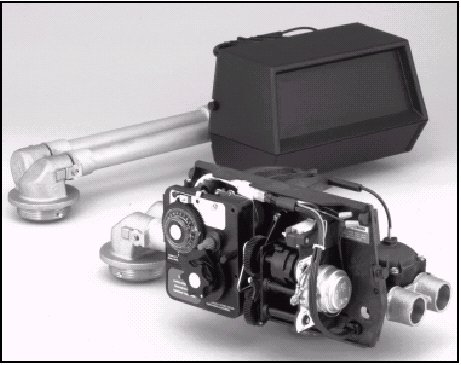
| Model 9000 Econominder |
| Service Manual |
Installation Checklist
WATER PRESSURE: A minimum of 25 pounds of water pressure is required for regeneration valve to operate effectively.
ELECTRICAL FACILITIES: An uninterrupted alternating current (A/C) supply of 110V, 60Hz is required. Note: Other voltages are available. Make sure the current supply is always hot and and cannot be turned off with another switch.
EXISTING PLUMBING: Condition of existing plumbing should be free from lime and iron buildup. Piping that is built up heavily with lime and/or iron should be replaced. If piping is clogged with iron, a separate iron filter unit should be installed ahead of the water softener.
LOCATION OF SOFTENER AND DRAIN: The softener should be located close to a drain to prevent air breaks and back flow.
BY-PASS VALVES: Always provide for the installation of a by-pass valve if unit is not equipped with one.
CAUTION: Water pressure is not to exceed 120 psi, water temperature is not to exceed 110°F, and the unit cannot be subjected to freezing conditions.
1. Place the softener tank where you want to install the unit, making sure the tanks are level and on a firm base.
2. All plumbing should be done in accordance with local plumbing codes. The pipe size for the drain line should be minimum 1/2″. Overhead drains exceeding 4′ above unit require 3/4″ drain line.
3. Both tanks must be the same height and diameter and filled with equal amounts of media. The 1″ distributor tube (1.050 O.D.) should be cut flush with top of each tank.
4. Lubricate the distributor O-Ring seal and tank O-Ring seal with silicone lubricant. Place the main control valve on one tank and the tank adapter on the second tank.
5. NOTE: The 1″ copper tubing to interconnect the tanks must be soldered prior to assembly on the main control valve and tank adapter. There should be a minimum of 1″ distance between tanks on final assembly.
6. Solder joints near the drain must be done prior to connecting the Drain Line Flow Control fitting. Leave at least 6″ between the DLFC and solder joints when soldering. Failure to do this could cause damage to the drain module.
7. Teflon tape is the only sealant to be used on the drain fitting.
8. Make sure that the floor is clean beneath the salt storage tank and that it is level.
9. Place approximately 1″ of water above the grid plate (if used) in your salt tank. Salt may be placed in the unit at this time.
10. On units with a by-pass, place in by-pass position. Turn on the main water supply. Open a cold soft water tap nearby and let run a few minutes or until the system is free from foreign material (usually solder) that may have resulted from the installation.
11. Place the by-pass in service position and let water flow into the mineral tanks. When water flow stops, open a cold water tap nearby and let run until air pressure is relieved.
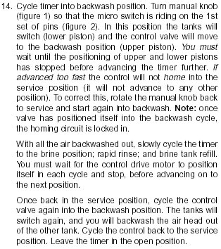
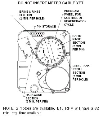
12. Electrical: All electrical connections must be connected according to codes. Plug unit into electrical outlet. Do not insert meter cable into the meter yet.
Regeneration Cycle Program Setting Procedure
(Brine Tank Refill Separate From Rapid Rinse)
Time Brine Refill and Meter Setting Procedure
Programming
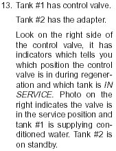
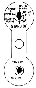
1. Your control valve has been factory set for backwash; brine and slow rinse; rapid rinse and brine
tank fill times. Any of these times can be changed by repositioning the pins and holes or adding
more pins. Note that two different speed timer motors are used, one allows for an 82
minute maximum regeneration time (each pin or hole = 1 min.). The other allows for 164 minute
maximum regeneration time (each pin or hole = 2 min.).
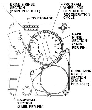
2. The 9000 Control has a separate brine tank fill cycle. Your desired salt setting must be
calculated, using the blue (.25 gpm) or black (.5 gpm) or red (1.0 gpm) rate of refill (in gpm)
times your timer setting. Then using one gallon of fresh water dissolving approximately 3 lbs. salt,
calculate your refill time.ie: A desired 9 lb. salt setting: The unit has a .5 gpm refill rate, we will need a 3 gallon fill. (3 gal.
x 3 lb./gal. = 9 lb.salt). The timer refill section would have to be set at 6 minutes. (6 min x .5
gpm = 3 gal. fill)
Note: There always must be 2 pins at the end of your refill time. This is to stop the fill cycle.
With your regeneration times now set, place timer back to its original position, making sure
the lower right hand corner snaps back into the backplate and the meter cable slides
through the backplate and does not bind.
3. Setting the gallon wheel Knowing the amount of resin you have in each tank and your salt setting
per regeneration, calculate the gallons available, using the following capacities as a guide:
One Cubic Foot of Resin
Salt Setting at
Capacity per Regeneration
15 lb 30,000 grains 10 lb 27,000 grains 8 lb 24,000 grains 6 lb 20,000 grains
Gallons available = Capacity per Regeneration
Compensated Hardness of H2O
ie: 24 grain water; each tank having 1 cubic foot of resin and salted at 8 lb. of salt, yielding a
usable 24,000 grain capacity: 1,000 gallons available = 24,000 gr. capacity
24 gr. water
DO NOT SET THIS FIGURE - GO TO STEP 4
3. Since the 9000 Valve regenerates with soft water from the other tank, you must subtract the
water used for regeneration. Take each of your regeneration cycles and calculate the water used.
ie: Unit is set up for a 10 tank having 2.4 gpm backwash, #1 injector, .5 gpm refill, timer set up for
8 min. backwash, 54 min. brine and rinse, 6 min. rapid rinse, 6 min. brine tank fill.
A. Backwash - 8 mins. x 2.4 gpm = 19.2 gallons
B. Brine and Rinse - 54 mins. x .33 gpm = 17.8 gallons
C. Rapid Rinse - 6 mins. x 2.4 gpm = 14.4 gallons
D. Brine Tank Fill - 6 mins. x .5 gpm = 3.0 gallons
Total Regeneration Water = 54.4 gallons
If we have 1000 gallons available from Step 3, we want to subtract the regeneration water used from the total water available.
1000 gallons available - 55. gallons used = 945 gallons setting (in regeneration)
4. NOW set Meter wheel at approximately 950 gallons. Lift the inner dial of the meter program wheel
so that you can rotate it freely. Position the white dot opposite the 950 gallon setting
NOTE: There is a slight delay time from the time the meter zero’s out and when the cycle starts.
Units using the 1/15 rpm motor, 82 minute regeneration time available (tanks 6″ thru 12″)
have a 9 minute delay. Units using the 1/30 rpm motor, 180 minute regeneration time
available (tanks 13″ and larger) have an 18 minute delay.
Typically on residential equipment this delay period is not critical. On commercial
applications, this must be taken into consideration and continuous flows for 9 minutes or 18
minutes should be subtracted from water available.
NOW 1. Insert Meter cable into Meter.
2. Check Bypass.
3. Plug unit in.
Learn more about the Aboite New Trails recreation pathways
Links
All information is believed to be true and accurate to the best of our knowledge at the time of publishing, however, we do not warrant or guarantee any of the information shown on this web site. Visit our sponsor for replacement water filters and reverse osmosis systems at WaterFiltersOnline.com.